AGA Oil Control Valve Instructions: A Comprehensive Guide
This guide details AGA oil control valve operation, maintenance, and troubleshooting, ensuring efficient heating. It covers installation, automatic/manual modes, and safety precautions for optimal performance.
Understanding the AGA Oil Control Valve
The AGA oil control valve is a critical component within AGA cooker systems, regulating oil flow to maintain consistent and efficient heating. Originally transforming cooking methods, AGA cookers rely on precise oil delivery for optimal performance. This valve manages the fuel supply, switching between automatic and manual control modes.
Understanding its function is key to ensuring your AGA cooker operates safely and effectively. Proper operation involves opening all valves in the oil feed line, from the storage tank to the burner control box. Regular checks and maintenance, as outlined in AGA resources, are vital for longevity.
Purpose of the Oil Control Valve
The primary purpose of the AGA oil control valve is to precisely regulate the amount of oil delivered to the burner, ensuring stable and efficient combustion. It governs the heat output, allowing for adjustments between high and low fire settings. This control is achieved through both automatic operation, managed by the cooker’s internal systems, and manual adjustments via the control knob.
Effectively, the valve acts as the heart of the AGA’s heating system, responding to temperature demands and maintaining consistent warmth. Ensuring all valves along the oil feed are open is crucial for proper function.
AGA Oil Control Valve Components
The AGA oil control valve comprises several key components working in harmony. These include the valve body, housing the internal mechanisms responsible for oil flow regulation. A crucial element is the control knob, enabling manual adjustment between automatic and manual modes, and controlling the heat output. The valve also integrates a manual/automatic switch for operational flexibility.
Furthermore, support brackets are essential for secure mounting, and flexible couplings connect the valve to the oil feed pipe. Specific models, like the BM30B895AGA, may include additional parts for TempoMat integration.
Valve Body and Internal Mechanisms

The valve body serves as the central housing for the AGA oil control valve’s intricate internal mechanisms. These mechanisms precisely regulate oil flow to the burner, ensuring consistent and efficient heating. Internal components work together to respond to control signals, whether from the automatic system or manual adjustments via the control knob.
Proper functioning relies on clean oil and unobstructed pathways within the valve. Regular inspection and cleaning are vital to maintain optimal performance and prevent operational issues. The body’s construction ensures durability and reliable oil control.
Control Knob and Manual/Automatic Switch
The control knob allows for manual adjustment of the oil flow, enabling precise temperature control. Rotating the knob to the MK6 position is a key step in initial setup, ensuring correct operation. The manual/automatic switch dictates whether the valve responds to the automatic control system or direct user input.
Switching to automatic mode allows the AGA cooker to maintain a consistent temperature. In manual mode, the user has complete control, overriding the automatic settings. Always ensure oil valves are open before operation.
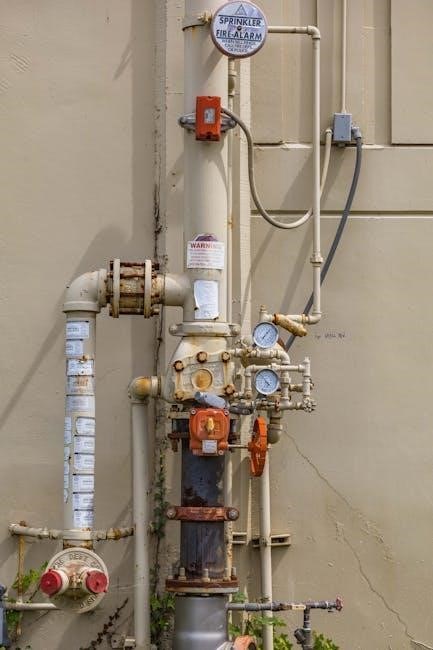
Oil Supply System Integration
Proper integration with the oil supply is crucial for reliable AGA operation. This begins with a secure connection to the oil storage tank, ensuring a consistent fuel source. All valves along the oil feed pipe, from the tank to the burner oil control box, must be fully open to facilitate smooth oil flow.
Careful installation of the oil feed pipe is essential, avoiding kinks or obstructions. The pipe should be securely fitted to the control valve, preventing leaks. Regular inspection of the entire system is recommended to maintain optimal performance and safety.
Connecting to the Oil Storage Tank
Establishing a secure link to the oil storage tank is the first step in a functional AGA oil supply system. Ensure the tank is appropriately sized for your heating needs and complies with local regulations. The connection point must be clean and free from debris to prevent contamination of the oil supply.
Utilize approved fittings and hoses designed for oil transfer, verifying compatibility with your tank and AGA valve. Regularly inspect the connection for leaks or signs of wear, addressing any issues promptly to maintain a safe and efficient system.
Oil Feed Pipe Installation
Proper installation of the oil feed pipe is crucial for reliable AGA operation. Route the pipe carefully, avoiding sharp bends or kinks that could restrict oil flow. Secure the pipe adequately to prevent sagging or movement, utilizing appropriate supports and clamps.
Ensure the pipe is correctly sized for the distance and flow rate required by your AGA model. All joints must be airtight to prevent leaks and maintain consistent pressure. Before connecting to the control valve, thoroughly flush the pipe to remove any debris or contaminants.
AGA Oil Control Valve Operation
The AGA oil control valve governs fuel delivery to the burner, enabling precise temperature regulation. It functions in both automatic and manual modes, offering flexible control. In automatic mode, the valve responds to thermostat settings, maintaining consistent heat. Manual control allows direct adjustment of the oil flow via the control knob, useful for initial setup or specific heating needs.
Regularly check the valve’s responsiveness to ensure accurate operation. Understanding these modes is key to maximizing efficiency and maintaining a comfortable environment.
Automatic Mode Functionality
In automatic mode, the AGA oil control valve seamlessly integrates with the cooker’s thermostat, delivering a consistent and pre-set temperature. The valve opens and closes automatically, regulating oil flow based on the room’s thermal requirements. This eliminates the need for manual adjustments, providing convenient and efficient heating. Ensure all valves on the oil feed pipe are open for proper function.
The system responds to temperature fluctuations, maintaining a stable and comfortable environment. Proper operation relies on a functioning electric supply to the valve.

Manual Control Operation
For manual operation, turn the control knob to the desired setting – from low fire to maximum. This overrides the automatic thermostat, allowing direct control over the oil flow and heat output. Turning the knob fully anti-clockwise initiates manual control. This is useful for quickly achieving a specific temperature or for initial start-up.
Remember to monitor the cooker closely when using manual control, as temperature adjustments are not automated. Lift the control knob to the MK6 position before adjusting.
Checking Low Fire Settings
To verify correct low fire operation, turn the control-regulating knob to the designated low fire position. Observe the flame; it should be small and stable, providing minimal heat output. This setting ensures efficient simmering and maintains a consistent low temperature. Proper low fire adjustment is crucial for economical operation and prevents overheating during extended periods.
Ensure all oil valves are open and oil is present in the control valve before testing; If the flame is too large or unstable, adjustments may be needed to the valve’s internal settings.
Troubleshooting Common Issues
If the valve fails to open or close, first check the electric supply and ensure the manual/automatic switch is correctly positioned. Oil supply problems, such as a blocked filter or empty tank, are frequent causes of operational issues. Verify all valves along the oil feed pipe are fully open.
A weak or absent flame often indicates insufficient oil delivery. Inspect the oil feed pipe for kinks or obstructions. If problems persist, consult a qualified technician for a thorough inspection and potential valve replacement.
Valve Not Opening/Closing
If the AGA oil control valve isn’t responding, begin by verifying the electrical connection – ensure a stable power supply reaches the unit. Confirm the control knob is set to the desired position (MK6 for initial setup). A faulty manual/automatic switch can also prevent operation; test its functionality.
Inspect for blockages within the valve itself, and check if all upstream oil valves are fully open. If issues continue, a professional assessment is recommended to diagnose potential internal valve failures or electrical component malfunctions.
Oil Supply Problems
Insufficient oil supply is a common issue; first, confirm adequate oil levels in the storage tank. Inspect the oil feed pipe for kinks, blockages, or leaks that could restrict flow to the control valve. Ensure all valves along the oil line, from the tank to the burner oil control box, are fully open.
A clogged oil filter can also starve the valve; regular cleaning is crucial. If problems persist, consider a professional inspection of the entire oil supply system to identify and rectify any underlying issues.
Maintenance and Cleaning
Regular maintenance extends the AGA oil control valve’s lifespan and ensures optimal performance. Implement routine inspection procedures, checking for leaks, corrosion, and proper operation of the manual/automatic switch. Prioritize cleaning the valve and its integrated filter to prevent blockages from sediment or oil residue.

A clean valve ensures consistent oil flow and efficient combustion. Follow the manufacturer’s guidelines for cleaning solutions and procedures, and always disconnect the power supply before undertaking any maintenance tasks.
Regular Inspection Procedures
Consistent inspection is crucial for AGA oil control valve reliability. Visually examine the valve body for any signs of oil leakage, corrosion, or physical damage. Check the control knob and manual/automatic switch for smooth operation and secure attachment. Ensure all oil valves along the feed pipe are fully open.
Verify the support bracket is firmly secured, preventing undue stress on the valve. Regularly inspect the oil storage tank level and the condition of the oil feed pipe for cracks or blockages. Document all inspection findings for future reference.
Cleaning the Valve and Filter
Periodic cleaning maintains optimal AGA oil control valve performance. Before cleaning, ensure the oil supply is shut off and the valve is isolated. Carefully disassemble the valve, noting the position of all components. Clean the valve body and internal mechanisms with a suitable solvent, removing any oil residue or debris.
Pay close attention to the filter, cleaning it thoroughly to prevent blockages. Inspect the control knob and switch for grime and clean as needed; Reassemble the valve carefully, ensuring all parts are correctly positioned before restoring the oil supply.
AGA Oil Control Valve Replacement
Replacing an AGA oil control valve requires careful attention to detail. First, identify the correct replacement valve – BM 30B895AGA is a common model. Shut off the oil supply and disconnect the existing valve. Carefully detach the oil feed pipe, noting its connection points for reattachment.
Install the new valve, ensuring a secure fit and proper alignment. Refit the oil feed pipe, tightening connections to prevent leaks. Verify all connections are secure before restoring the oil supply and testing the valve’s operation.
Identifying the Correct Replacement Valve
Selecting the right replacement AGA oil control valve is crucial for proper function. The model BM 30B895AGA is frequently used, but verifying compatibility with your specific AGA cooker is essential. Consider the cooker’s age and any previous modifications.
Check existing valve markings or consult AGA documentation for the correct part number. Electric top compatibility may require a specific valve version (AO2M220022 for spares). Ensure the replacement includes necessary couplings and a flexi top if needed, referencing item 6 in relevant parts lists.
Refitting the Oil Feed Pipe
Carefully refit the oil feed pipe to the newly installed control valve, ensuring a secure and leak-proof connection. Before connecting, inspect the pipe for any damage or wear, replacing it if necessary. Tighten all fittings adequately, but avoid over-tightening, which could cause damage.
Double-check that all valves on the oil feed pipe, from the storage tank to the burner oil control box, are fully open. This ensures a consistent oil supply. After refitting, prime the system according to AGA’s instructions to eliminate airlocks and confirm proper oil flow.

Support Bracket and Valve Mounting
The AGA oil control valve offers flexible mounting options, allowing installation on either the left or right side of the cooker. Alternatively, it can be positioned at a convenient location adjacent to the cooker, provided it remains within the same room. Utilize the provided support bracket to securely mount the valve, ensuring stability and preventing strain on the oil feed pipe.
Proper mounting minimizes vibration and potential leaks. Ensure the bracket is firmly attached to a solid surface. Consider accessibility for future maintenance when selecting the mounting position. Refer to AGA documentation for specific bracket installation guidelines.
Electric Top Compatibility
AGA oil control valves are designed for compatibility with both standard and electric top models. When integrating with an electric top, ensure the oil control valve is correctly configured for the specific cooker type. Certain electric top models require a dedicated valve setup, potentially utilizing a separate ‘Electric Top Only’ component (replacing AO2M220022 for spares).
Verify the correct valve and coupling configuration before installation to avoid operational issues. Consult the AGA documentation specific to your electric top model for detailed compatibility information and wiring diagrams. Proper integration ensures seamless operation between the oil supply and electric heating elements.
TempoMat Integration
The AGA TempoMat system offers automated oil firing control for enhanced efficiency. Integration involves utilizing the TempoMat 12V BM334 unit, which is often included as a component with specific valve packages. This system regulates oil consumption based on cooker demand, optimizing fuel usage and maintaining consistent temperatures.
Ensure correct wiring and configuration of the TempoMat unit with the oil control valve. The BM334 model is specifically designed for 12V systems. Proper installation and calibration are crucial for reliable operation and maximizing the benefits of automated oil control provided by the TempoMat system.
TempoMat 12V BM334 Details
The TempoMat 12V BM334 is a dedicated control unit for AGA oil-fired cookers, designed to automate the firing process. It’s frequently included within TempoMat 12V kits, streamlining installation. This unit manages oil supply based on temperature settings, enhancing efficiency and reducing fuel waste.
Key features include precise temperature regulation and compatibility with standard 12V systems. Proper installation requires careful attention to wiring diagrams and calibration procedures. The BM334 optimizes performance by automatically adjusting the oil flow, ensuring consistent cooking temperatures and minimizing manual intervention.

AGA Membership and Resources
AGA membership provides access to a wealth of resources for owners and technicians, supporting optimal cooker performance and longevity. Members benefit from the latest guidance on maintenance, troubleshooting, and safety procedures related to oil control valves and broader AGA systems.
The AGA organization is a trusted voice in the GI community, offering educational materials and a network of experts. Resources include downloadable manuals, FAQs, and direct access to support for resolving technical challenges. Membership empowers owners to maintain their cookers effectively and ensures access to qualified service professionals.
Safety Precautions
Prioritize safety when working with AGA oil control valves and the oil supply system. Always ensure all electrical supplies are disconnected before commencing any maintenance or repair work. Never attempt repairs if you are not a qualified technician, as improper handling can lead to fire hazards or oil leaks.
Regularly inspect the oil feed pipe and valve connections for signs of wear or damage. Ensure adequate ventilation in the area surrounding the cooker. Familiarize yourself with emergency shutdown procedures and keep a fire extinguisher readily accessible. Adhering to these precautions ensures safe operation.